
Blue-light 3D scanning for small parts
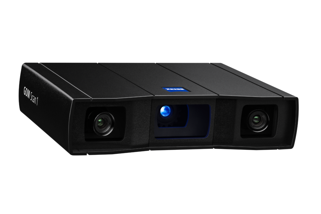
GOM Scan 1
Turn physical components into 3D data for inspection, reverse engineering and 3D printing. GOM Scan 1 combines a compact mounted scanner with ZEISS INSPECT, helping you capture surface geometry and put the results to work.

Three sensor versions
Choose MV100, MV200 or MV400 around your components and features.
Compact, mounted setup
Position the scanner on a tripod, desk stand or ScanPort.
ZEISS INSPECT
Process meshes, compare geometry with CAD and report inspection results.
Choose your scanner around the work you do
Start with a component and a clear idea of the result you need. Are you checking dimensions, recreating a part without CAD, or preparing a model for printing? Those requirements guide the scanner, software and setup.
Delta XD brings practical optical metrology experience to equipment selection, installation, training and ongoing support. We can work through the scanning approach with your team.
What it does
Capture geometry for the next engineering decision
A useful scan starts with knowing how the data will be used. For a replacement component, it may provide the geometry needed for CAD reconstruction. For inspection, the same surface data can be aligned to a reference and evaluated against defined requirements.
Capture accessible surfaces
Blue-light fringe projection records surface shape from a mounted position. Reposition the part or sensor to collect the views needed for coverage.
Monitor the sensor
The stereo camera principle supports continuous sensor monitoring during measurement, helping identify changes that could affect data quality.
Prepare a usable mesh
In ZEISS INSPECT, turn captured points into a polygon mesh, then refine or thin it for the intended task. Review hole filling carefully where geometry was not measured.
Plan for repeat work
A rotation table helps present different sides of a component. ScanPort adds programmed positioning for tasks where a repeatable scanning sequence is useful.

From captured shape to inspection results
Align the measured mesh to CAD or another suitable reference, then use surface comparisons, sections and dimensional checks to answer the inspection question. Record the alignment and tolerances alongside the results.
Automatic surfacing can create CAD surfaces from the mesh with suitable software. For redesign or manufacture, full reverse engineering can reconstruct the product’s design intent, interpreting wear or damage and rebuilding the intended features and dimensions.
Measuring volumes
Choose the version around your smallest important feature
GOM Scan 1 is available as three separate sensor versions: MV100, MV200 and MV400. Each has a fixed measuring volume, so choosing the right version is part of specifying the system.
A smaller measuring area gives closer point spacing; a larger area covers more surface in each capture. Consider both the component size and the features you need to resolve.
| Version | Measuring area | Point spacing | Example tasks |
|---|---|---|---|
| MV100 | 100 × 65 mm | 0.037 mm | Small components, fine features and detailed geometry |
| MV200 | 200 × 125 mm | 0.060 mm | Small manufactured parts, brackets and housings |
| MV400 | 400 × 250 mm | 0.129 mm | Broader coverage of medium-sized components, models and castings |
The measuring areas shown describe a single capture, not maximum overall part sizes. Application examples are starting points for discussion. Point spacing describes sampling and is not a statement of measurement accuracy.
Measurement workflow
Prepare, scan and evaluate
Define the output first: a mesh for printing, geometry for CAD reconstruction, or an inspection report. Plan how the part will be supported and referenced, then check the surface finish and optical access.
Capture enough views to cover the required geometry. After combining the scans, review the mesh before editing or evaluating it. Save the inspection setup and reporting approach where the task will be repeated.

Applications
Inspect a part. Recreate its shape. Develop the next version.
Check a moulded component against CAD, capture an existing part for redesign, or prepare a physical model for 3D printing. GOM Scan 1 provides surface data for these different tasks; the processing and evaluation should follow the output you need.
For manufactured parts, discuss the critical dimensions and tolerances with us. For reverse engineering and printing, consider which details must be preserved and what further CAD or mesh work is required.
Technical data
GOM Scan 1 specifications
Compare the three versions using the published measuring areas, point spacing and working distances.
| Characteristic | GOM Scan 1 (100) | GOM Scan 1 (200) | GOM Scan 1 (400) |
|---|---|---|---|
| Points per scan | 6 million | 6 million | 6 million |
| Working distance | 400 mm | 450 mm | 500 mm |
| Sensor weight | Approx. 2.5 kg | Approx. 2.5 kg | Approx. 2.5 kg |
| Sensor dimensions | 290 × 215 × 80 mm | 290 × 215 × 80 mm | 290 × 215 × 80 mm |
| Light source | LED | LED | LED |
| Connection | USB 3 | USB 3 | USB 3 |
| Cable length | 5 m | 5 m | 5 m |
These are published sensor specifications. They do not establish the accuracy achievable on every component. Confirm the measurement requirements, software licence and workstation specification when configuring your package.
Scanning setups
Ways to use GOM Scan 1
Choose a mounting arrangement around the component, available space and frequency of scanning. GOM Scan 1 can be used on a tripod, a desk stand or ScanPort.
Tripod

A flexible arrangement when the sensor needs to be positioned around the part. Suitable for a dedicated measurement area or taking the compact system to another work location.
Desk stand

A compact setup for smaller components on a workbench. A suitable rotation table can help present different sides of the part while keeping the scanner mounted in place.
ScanPort

Available for MV200 and MV400, ScanPort adds motorised sensor positioning. Combined with a ROT 350 table, it supports recurring scanning sequences. Motion Replay requires ZEISS INSPECT Optical 3D Pro; confirm the complete configuration with us.
GOM Scan 1 questions, answered
Is GOM Scan 1 right for your application?
Can I change between measuring volumes?
No. Each GOM Scan 1 sensor has one fixed measuring volume. Choose MV100, MV200 or MV400 around the coverage and detail your work requires. If changing lenses is important, discuss ATOS Q with us.
How should I compare scanner accuracy?
Do parts need scanning spray or reference points?
That depends on the surface, geometry and scanning strategy. Reflective or transparent finishes may need preparation, and referencing must support combining the views. A representative component helps establish the approach.
Will it create an editable CAD model?
How does it differ from ATOS Q?
GOM Scan 1 captures 6 million points per scan and comes in three fixed measuring volumes. Its point spacing is 0.037 mm (MV100), 0.060 mm (MV200) or 0.129 mm (MV400). ATOS Q offers 8M and 12M versions with interchangeable measuring volumes, giving more flexibility over coverage and detail resolution. Finer point spacing helps capture smaller features, but the measuring volume matters as well as the point count. Point spacing is not measurement accuracy. We can compare the systems on your component and the detail you need to resolve.
Is ScanPort included in the starting package?
No. The starting package includes a tripod with swivel head stand and ZEISS INSPECT Essential Line software. ScanPort is a separate configuration option. Your quotation will confirm the sensor version and all supplied items.
GOM Scan 1 pricing and packages
GOM Scan 1 from £19,078
Includes one measuring volume, a tripod with swivel head stand, a thermometer and ZEISS INSPECT Essential Line software.
Excludes VAT, delivery, training, setup and installation.
Your quotation will confirm the selected sensor version and supplied items. Download the GOM Scan 1 brochure for an introduction to the system.
Build your package around the task
Tell us what you want to scan, the features that matter and how you will use the results. We will help define a suitable configuration.
Discuss your GOM Scan 1 requirements
Tell us about your components, the detail or dimensions that matter, and the outputs you need. Request pricing or arrange a demonstration with Delta XD.
