
When engineers test a component, understanding how it moves, bends or deforms under load is an important part of assessing its performance. Digital Image Correlation (DIC) is a non-contact optical measurement technique that uses cameras and specialist software to track these changes, providing detailed information about how materials and structures behave during testing. From measuring strain in a material sample to analysing the movement of an aircraft wing, DIC allows engineers to capture and understand movement that might otherwise be difficult to measure or even see with the naked eye.
How does Digital Image Correlation work?
The basic principle behind DIC is surprisingly straightforward: take a series of images, identify recognisable features and track how those features move from one image to the next. Imagine drawing a small pattern on a rubber band, photographing it, then stretching it and taking another photograph. By comparing the two images, you could work out how far different parts of the pattern have moved and how much the rubber band has stretched.
DIC works on a similar principle, using digital cameras and software to make these measurements across a component’s surface. The software identifies features based on their contrast, shape, size and surrounding image patterns. As the component moves or deforms, it follows these features through the image sequence to calculate their changing positions. When enough surface information is captured, the software can build a detailed picture of how the component behaves over time.
2D vs 3D Digital Image Correlation
DIC can be performed in either two or three dimensions, depending on the camera arrangement and what needs to be measured.
2D DIC: Measuring movement in a flat plane
A 2D DIC system typically uses a single camera positioned directly in front of the test object. Before testing, a scale is established so the software knows what distance each pixel represents in real-world measurements. For example, if a known distance covers 100 pixels in an image, the software can use that relationship to convert tracked pixel movement into millimetres. This works well when the surface is flat, remains perpendicular to the camera and moves within the image plane. However, if the object moves towards or away from the camera, that movement can affect the apparent size and position of features in the image, introducing measurement errors.
3D DIC: Measuring movement in three dimensions
For more complex movement, a 3D DIC system uses two cameras positioned at different angles, known as a stereo camera arrangement. Think of it as being similar to human vision. Because our eyes see an object from slightly different perspectives, our brain can judge its depth and position.
A stereo DIC system uses the same underlying principle. Once the cameras have been calibrated, the software knows their relative positions and viewing geometry. It can then identify matching features in both camera images and use triangulation to calculate their positions in 3D space. Triangulation is simply a mathematical method of determining a position using observations from different viewpoints. This allows engineers to measure movement in all three spatial directions, including movement towards and away from the cameras. Systems such as ARAMIS use this approach to measure 3D displacement, deformation and surface strain during testing.
How does DIC know what to track?
For image correlation to work, the software needs recognisable features that it can reliably identify as the object moves. There are several ways to achieve this, depending on the measurement required.
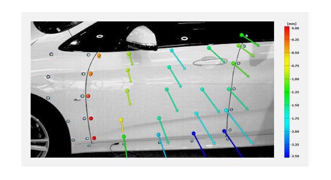
1. Tracking points (reference markers)
Reference markers are small, high-contrast targets placed on the surface of a component. The software identifies each marker and follows its position throughout the test This is particularly useful when engineers want to understand how specific points move, or how an entire component changes position and orientation. For example, markers placed on a moving mechanism could be used to measure its position, rotation, speed and acceleration.
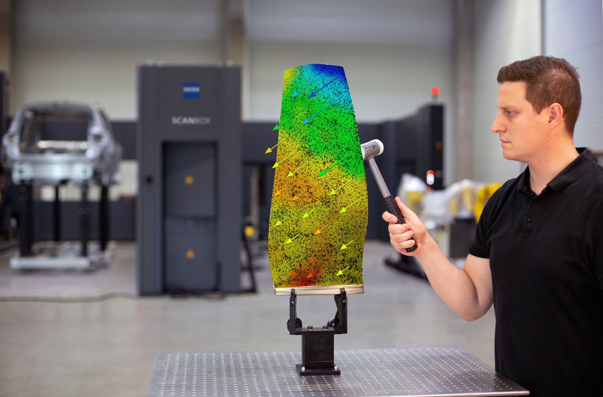
2. Speckle patterns
For full-field DIC, the surface is typically covered with a random, high-contrast pattern, often made up of black and white speckles. The pattern gives the software thousands of recognisable areas to track across the surface. Rather than simply measuring a few individual points, the software compares small groups of pixels, often called facets or subsets, to determine how different areas move relative to one another. This makes it possible to calculate deformation and strain across the visible surface. The random nature of the pattern is important because each small area needs to be distinguishable from its neighbours.
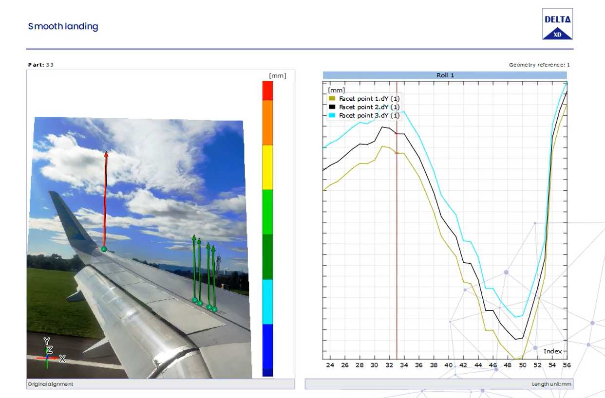
3. Natural surface features
Sometimes, a component already has enough visible texture or contrast for the software to track its movement without applying additional markers or paint. These naturally occurring features might include surface markings, texture or other recognisable patterns.
Whether they’re suitable depends on the surface, lighting, image quality and type of measurement being performed. Natural features can be particularly useful for motion tracking, although they may not provide the consistent pattern needed for reliable full-field strain measurement.
What can Digital Image Correlation measure?
One of the biggest advantages of optical measurement is the amount of information that can be extracted from a single test.
Depending on the camera arrangement, tracking method and analysis software, DIC and related optical tracking techniques can provide:
- Position and displacement: Where a point or surface is located and how far it moves.
- Angles and rotation: How a component changes orientation during movement.
- Speed and acceleration: How quickly something moves and how its speed changes over time.
- Surface strain: How much a material stretches, compresses or deforms relative to its original dimensions.
- Rigid-body movement: How an object moves or rotates as a whole, without considering changes to its shape.
- Crack propagation: How a visible crack develops and progresses through a material during testing.
- CAD model motion tracking: Using measured movement to animate a digital model and visualise how a component behaves.
- Finite Element Analysis (FEA) validation: Comparing physical test measurements with predictions from computer simulations.
It’s worth remembering that not every measurement requires full-field DIC. Tracking a handful of reference markers can tell you a great deal about a mechanism’s movement, while a speckle pattern is more appropriate when you need to understand how strain is distributed across a surface.
Where is Digital Image Correlation used?
DIC is used across engineering research, product development and testing, particularly when understanding a component’s behaviour under real conditions is important.
Material testing
During tensile, compression or bending tests, DIC can show how strain develops across a material sample. Rather than measuring deformation at just one location, engineers can examine the strain distribution across the visible surface and identify areas where deformation is concentrated. This can help with material characterisation and understanding how a material responds to loading.
Structural and component testing
Large structures and complex components don’t always deform in simple, predictable ways. DIC can be used to investigate how a structure bends, twists or changes shape when subjected to different loads. For example, measuring the movement of an aircraft wing during testing can help engineers understand its deformation and compare the measured response with design predictions.
Impact and high-speed testing
Some engineering events happen in a fraction of a second. With suitable high-speed cameras and measurement software, optical tracking and DIC can capture movement and deformation during rapid events such as impacts, deployments and dynamic loading. The resulting image sequences can be analysed to understand what happened, where movement occurred and how the component responded over time.
Validating engineering simulations
Computer simulations are widely used to predict how components will behave, but those predictions still need to be checked against physical tests. DIC provides measured displacement and strain data that engineers can compare with results from Finite Element Analysis (FEA). If the simulation predicts deformation in one area but the physical test shows something different, that information can help engineers investigate the model, material assumptions or test conditions.
What are the advantages of DIC?
One of DIC’s most useful features is that it’s a non-contact measurement technique.
Traditional measurement methods, such as strain gauges, often require sensors to be physically attached to a component. DIC instead observes the surface using cameras, although the surface may still need markers or a speckle pattern. For full-field measurements, this also means engineers can examine deformation across a large number of locations rather than relying solely on individual measurement points. Other advantages include the ability to analyse complex 3D movement, capture changes over time and produce visual results that make deformation easier to understand.
Of course, DIC has its limitations. The cameras need a clear view of the measurement area, appropriate lighting and suitable surface contrast. Camera calibration, image resolution and the test environment all influence the quality of the results. Choosing the right set-up is therefore an important part of obtaining useful measurements.
Digital Image Correlation with ZEISS ARAMIS
At Delta XD, we use ZEISS ARAMIS optical measurement systems to investigate how materials, components and structures behave during testing. The ARAMIS range supports a variety of measurement applications, from tracking individual points and component movement to analysing full-field displacement and strain. By combining camera-based measurement with analysis software, engineers can examine test results visually, investigate areas of interest and compare measured behaviour with engineering simulations.
Our team works with this technology across a range of testing applications, helping customers choose an appropriate measurement approach and understand what the resulting data tells them.
Understanding how things move
Digital Image Correlation gives engineers a way to look beyond what a component appears to be doing and measure how it actually behaves. Whether you’re investigating material strain, tracking a moving mechanism or checking the accuracy of a simulation, the principle remains the same: capture the movement, analyse the images and turn that information into useful engineering data. And once you start looking at everyday objects through the lens of DIC, you’ll probably find yourself wondering how much they’re moving too.
Interested in exploring DIC further?
Learn more about Delta XD’s Digital Image Correlation services or explore the ZEISS ARAMIS range.
